English
Chinese
Introduction
In our previous article (“Force Sensing Essentials”) we discussed the increasing need for improved Human-Machine Interfaces (HMIs), especially in automotive design. The foundation of developing simpler, safer, and less intrusive HMI is that of the Smart Surface based on next-generation force sensors.
Miniaturized force sensors have been recently introduced that are integrated into IC silicon. These Micro-Electro-Mechanical Systems (MEMS) force sensors offer high-value low-cost force sensing and can be broken into two technologies: A) piezoresistive DC and B) piezoelectric AC.
Piezoresistive DC (we will refer to here as DC) force sensors for automotive applications have been on the market for several decades and have the classic challenges that all resistive strain sensors encounter, more detail to follow.
Piezoelectric AC (which we will refer to as AC) is a new, more modern approach to force sensing, and is based on technology developed by UltraSense Systems, Inc. In this article, we’ll contrast these two force sensor technologies.
First, let’s review the mechanics behind common force sensor implementations.
Solid-State Force Mechanics
A force sensor is basically a strain gauge located at a critical point in the path of mechanical travel (depending on the type of strain gauge — see “Force Sensor Technology” below). The combination of the mechanical interface and the strain gauge creates a virtual solid-state button interface we call a touchpoint. A touchpoint in automotive HMI should consider both the force sensing technology and the A-surface mechanical design as a system.
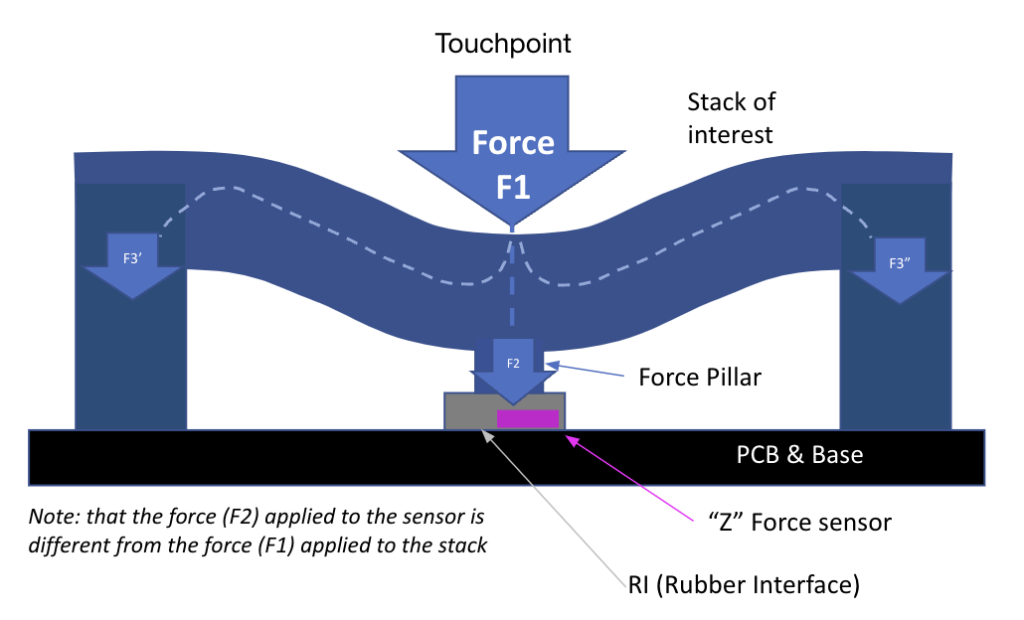
Two of the most common touchpoint designs are “Force Pillar” Z-strain sensing, which employs a dedicated pillar and rubber interface to activate the Z-force sensor, and “In-plane” (or direct lamination), which uses XY-strain sensing technology found in a typical “C channel” design.
Force Pillar Design (Z-strain)
The force pillar design implements a Z-force sensor, named appropriately because the force is applied along the Z axis. When automotive force sensors were costly, the force pillar design enabled one force sensor to operate with several adjacent buttons. While offering cost savings, there is a risk of the variability of consistent force that needs to be applied. For example, in a four-button row design that shares a single force sensor, buttons 2 & 3 may have a very consistent force, but 1 & 4 may require a greater force to trigger the same amount of strain.
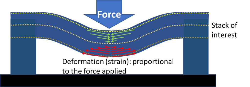
In-plane (XY-strain)
With in-plane designs, the A surface sits in the XY plane, and the strain sensor measures XY-strain deformation (Figure 2). The location of the supporting pillars impacts the deformation characteristics. In this example, the edge sidewalls act as surface supports that keep the large flat surface in place. An effective design provides optimal support for smooth deformation measurement.
Force Sensor Technology
MEMS force sensors are available in both AC and DC designs, and like other silicon-based technologies, they offer good price performance. Additionally, automotive-grade MEMS sensors pass AEC-Q100 specifications including temperature tolerance.
DC Force Sensor
First recognized in the 1950s, the modern silicon-based MEMS DC force sensor is based on the piezoresistive effect — the property of a material’s resistivity to change when subjected to a mechanical force. The DC piezoresistive Z-force sensors first appeared in automotive applications in the mid-2010s.
Because of the nature of the piezoresistive sensor, any deformation changes the resistance (and therefore the reported force) for as long as that deformation is present. This presents challenges in automotive assembly designs because the sensor must be recalibrated to compensate for changes in residual stress any time there is a change in assembly.
For example, a center console module delivered by a Tier 2 supplier is calibrated to that delivered module. When the module is inserted into a center console by the Tier 1 manufacturer, it would need to be recalibrated as a complete system. When the center console is subsequently inserted into the automobile for final assembly, new stresses may be introduced that require yet another calibration.
Challenges with DC force sensor implementation
There are several challenges with a DC force sensor implementation, we’ll discuss the two main ones: 1) mechanical design requirements and 2) residual stress.
Mechanical design requirements
The Z-force pillar design requires the addition of a pillar and rubber interface that transfers the force to the force sensor. That mechanical interface is subject to material deformation due to temperature and humidity changes, necessitating multiple calibration events. In addition, it is subject to wear and tear that eventually reduces the effective life of the assembly.
Furthermore, the Z-force sensor mechanical design is optimized for delivering uniformity across a module of buttons, necessitating additional pillar(s). The larger the assembly, the more pillars required; this often translates to modules with greater thickness in order to maintain performance consistency.
Residual Stress
The primary challenge of embedding a DC force sensor in an assembly is residual stress. Residual stress is a by-product of cumulative manufacturing tolerances that create different combinations of pressures on an assembly. Those pressures put “phantom” pressures on the force sensor that can skew the stress values that are reported — or overload the sensor such that the range of the sensor is exceeded (Figure 3).
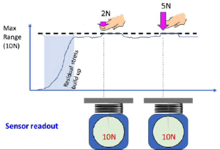
The challenge is that if the DC sensor scale cannot sit freely, as is the case in a system assembly in a car, the residual stress affects measurement accuracy because it can’t effectively get “zeroed out.” The residual stress can be compensated for during assembly, but throughout the life of the system, there will be limitations on its force-sensing capability.
The bottom-line difficulty with the DC sensor is that it might look good in the lab or in prototyping, but once in mass production, the issues of residual stress and tolerance start to show. By then, it’s probably too late to make a change, and customers will be forced to deal with the effects — including safety, cost, and recall issues.
AC Force Sensor
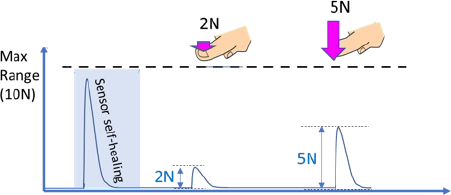
An AC force sensor is based on a solid-state, on-die piezoelectric transducer that measures strain by generating charge signals when it deforms (Figure 4). The key attribute of the transducer is that it seeks a charge-neutral state. As a result, after a deformation event, the transducer will “self-calibrate” by returning to a zero-volt state, even if the deformation persists (Figure 5).
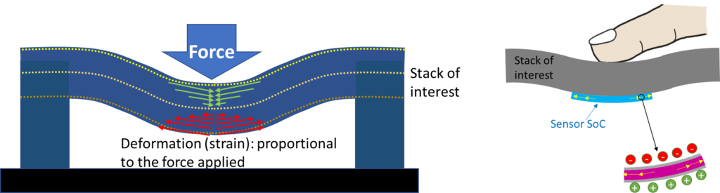
Further, the sensor only reacts to a “transient event” within a short amount of time — for example, a finger press — but rejects low-frequency events such as temperature drift or residual stress caused by assembly actions during manufacturing.
It is important to note that some AC force sensors such as the UltraSense AC force sensor can operate in both Force Pillar (Z-strain) and In-plane (XY-strain) mechanical designs. Operating in both mechanical designs gives the manufacturer the flexibility to support the broadest number of configurations — including legacy DC force and new in-plane designs.
Single vs Multiple Component Solution
Today’s force sensors require multiple components, three and more discrete parts that can result in a supply chain outage concerns. The traditional model involves
- Force sensor silicon
- Analog front-end silicon (AFE) semiconductor device that is used for signal conditioning that includes analog amplifiers, op amps, filters, and integrated circuits.
- Shared MCU to support driver software. More sensors add to the performance required of the MCU, and in HMI, the need to eliminate latency, the goal to have zero latency, particularly with haptics.
Note: For better performing multi-modal sensing, there would be an additional component to support the capacitive sensor silicon, and additional support driver software also running on a shared MCU driver support. If adding Illumination and haptics this all grows the number of necessary components to deliver a great touch experience..
New “all-in-one” single component solutions are now available where a single HMI controller silicon can replace the need for multiple components reducing supply chain risk where one component supply issue can cause the entire assembly to be put on hold. In addition to price-performance benefits, the shingle HMI controller can do more, offering
- Multi-modal Sensor Fusion (aka not just a force sensing component, but dual (two) sensor modes such as CapForce (capacitive and force) or UltraForce (ultrasound and force) in one part, this reduces supply chain concerns, highlighting the “power-of-one” part eliminates separate drivers, tuning and integration, with the sensor fusion data in one open platform.
- Integrated MCU to perform fast local processing that is not reliant on a multi-tasking shared MCU, this enhanced MCU-controller can have local AI-based Machine Learning algorithms that further enhance the touch interaction, by removing the unwanted accidental activation cases.
- Integrated feedback controls to drive lighting, audio, and haptics
- Secure connectivity options to directly support automotive connectivity protocols such as LIN or CAN
An example of this single HMI controller is the TouchPoint family of HMI controllers from UltraSense Systems. The CapForce mode supports capacitive and QuadForce sensing, operating under plastic and glass smart surfaces, and the UltraForce mode supports Ultrasound and QuadForce to support metals and other premium natural materials such as exotic woods.
Summary
In this article, we’ve illustrated the differences between DC force sensors developed by NextInput, Inc and AC force sensors from UltraSense Systems as used in automotive HMI applications. Legacy DC force sensors have inherent challenges, including demanding mechanical design requirements and issues related to residual stress. Newer technology AC force sensors are the most versatile, as they can be used in both Force Pillar (Z) and in-plane (XY) design applications.
Force Sensing technology comparison
Key feature checklist to look for in force sensing technology for automotive applications:
| Force SensorComparison MEMS technology and design applications | DC Force Sensor
Piezo Resistive |
AC Force Sensor
Piezo Electric |
| Force Pillar designs (Z-force sensing) |
||
| In-plane Sensing design (XY-force sensing) |
||
| Self-Calibration (Self-Healing) resolves residual stress issues and multiple calibrations | ||
| Single Component Solution | Force solution requires at least three components: DC MEMS Sensor, Analog Front End ASIC, Host MCU for SW Driver |
UltraSense is a single HMI controller with AC Force Sensing, MCU, Feedback and Connectivity All-In-One |
Table 1. Comparison of DC vs AC Force Sensing technologies.
All UltraSense Systems force sensors and TouchPoint HMI controllers use AC piezoelectric sensing, including the dual mode CapForce, UltraForce, and TapForce HMI controllers and the force-sensing only QuadForce sensor. (See the upcoming articles on HMI Controller MCU and Algorithms).
Questions or comments please give us feedback and we will share more objective details in future blog series. For more information, visit www.UltraSenseSys.com/go/blog