English
Chinese
Introduction
Good Human-Machine Interfaces (HMI) make interactions with your car simpler, safer, and less intrusive. At the same time there is an increasing number of new capabilities and sophisticated features that demand more controls than ever before. For the automobile, this is sometimes referred to as the CASE (Connected, Autonomous, Shared, and Electrified) revolution that is occurring in the automobile industry.
More controls introduce complexity that could look like a 747-airplane cockpit that requires a well-trained pilot to operate. To mitigate that situation, automakers are combining good interior cabin design with thoughtful user experience design while focusing on human factors and usability. New technology like Smart Surfaces can help by presenting only the features that are needed and adding controls that are hidden-then-lit. These capabilities have names like Shy Tech and Dead Face, but the message is: intelligent design with well-placed controls makes the difference.
Intelligent design includes making the interfaces smarter to adapt to the task at hand, reducing the button count yet enabling all the functions. This ability to place controls where they are needed are all attributes of good design in addition to good interface performance.
In this series of articles, we’re going to explore some new and better ways to implement Smart Surface HMI and how these new techniques can impact CASE opportunities.
Four Key Elements of Smart Surface HMI
We know that the next-generation HMI has multiple goals: it needs to be more accurate, intuitive, and manufacturable. But it goes beyond that—the HMI also needs to comprehend the entire ecosystem that surrounds it.
At UltraSense we’ve identified four key elements that need to be perfected to reach these goals:
- Sensing—detecting and reacting to a single external force isn’t enough—the sensor must be capable of accurately reporting a touch interaction regardless of stresses imposed during assembly and day-to-day or changes in temperature or humidity.
- Processing & Algorithms—sophisticated processing with Artificial Intelligence, specifically Machine Learning algorithms (AI ML) enables fusing multiple sensor data streams to improve accuracy and to “learn” what is an intended and unintended interaction.
- Feedback—is crucial in a user interface, particularly with respect to lighting, audio, and haptics.
- Secure Connectivity—the framework for delivering superior integration to other systems surrounding the HMI and permits on-the-fly updates or enhancement options.
This series of articles will examine solutions for each of these key elements.
We’ll begin with force sensing as part of “The Road to 100% Sensing” white paper series.
Types of Force Sensing
Force sensing in automotive Human-Machine Interface designs should consider the force sensing technology along with the A-Surface mechanical design and structure as a system.
Force Sensing Technology Compared
While there are many approaches to force sensing, the most common is the use of a resistance strain gauge. When the gauges in automotive are expected to pass AEC-Q200 passive component compliance to be suitable for harsh automotive environments, these passive components, are often incur notably higher component costs. Miniaturized force sensors have been recently introduced that are integrated into the IC silicon. These Micro-Electro-Mechanical Systems (MEMS) force sensors offer high value low-cost IC based force sensing and are broken into two categories: A) piezo-resistive DC and B) piezo-electric AC based technologies.
Force Sensing: Mechanical Design and Force Technology Relationship
Complementing force sensing technology is the mechanical designs often seen in automotive. Two of the most common designs are “In-plane” (or direct lamination), which uses XY strain sensing technology found in a typical “C channel” design or the “Force Pillar” Z strain sensing approach.
| Comparison of MEMS technology and design applications | 1) Force Pillar
Z Strain |
2) In Plane (Direct Lamination)
XY Strain |
| A] DC MEMS sensing | ||
| B] AC MEMS sensing |
Table 1. Comparison of MEMS technology and design applications
Generally, there are two automotive HMI force sensor A-surface mechanical design implementations:
- Force Pillar (adding a dedicated pillar and rubber interface to activate the Z force sensor)
- In Plane (using XY force sensing that measures force on the A-Surface vs from a force pillar)
Solid-State Force Mechanics
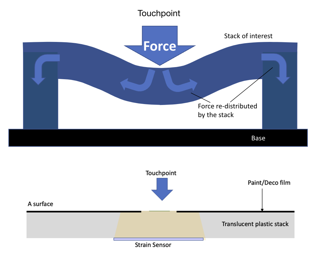
To create a virtual solid state button interface (we will call a touchpoint), a force sensor is connected to a device that measures strain, often called a strain gauge. The strain gauge is located adjacent to the touchpoint location, typically on the backside of an A-Surface and senses through the A-Surface thickness which we refer to as the mechanical “stack.”
When force is exerted downward, the force is re-distributed throughout the stack. The stack is held in place by some “anchor” which may be the sidewalls or adjacent support pillar structure(s). The touchpoint force is re-distributed into the sidewalls and adjacent support pillars holding the A-surface in place, and results in deforming the stack (Figure 1).
1] Force Pillar Design (Z Strain)
The Force Pillar design was implemented to support a “Z” force sensor (vs “XY”). There is the addition of a force pillar, an extra leg that connects to a RI (Rubber Interface) that maintains a consistent force to compensate for tolerance issues in mass production. These mechanical designs often have additional alignment pillars when using more touchpoints in an interaction area (multiple touchpoints in one part, for example a four-button touch bar).
When automotive force sensors were costly, the Force Pillar design enabled one force sensor to operate with several adjacent buttons. While offering a cost savings, there is the risk of variability of consistent force that needs to be applied. For example, in a four-button design that shares a single force sensor, buttons 2 & 3 may have a very consistent force, but 1 & 4 may require a greater force to trigger the same amount of strain. Additional stabilizer pillar/rails can add better mechanical consistency, but at the cost of more complex plastic parts. That additional complexity increases the risk of failure, from stiction to wobble, and increases size, resulting in the consumption of more plastic materials. The best force consistency is to have a force sensor for each button that is calibrated to the designated force target (e.g., 2N force), and with the cost reduction of MEMS, the solid-state force sensing delivers better performance and lower costs.
2] In Plane [XY Strain]
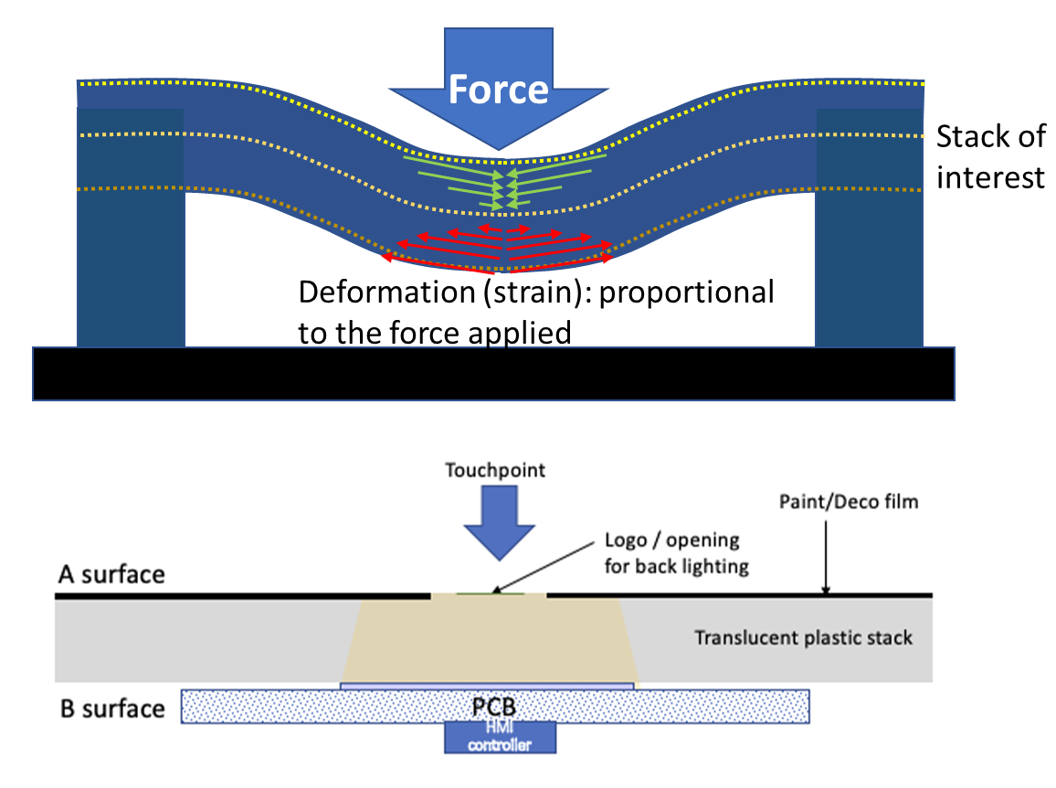
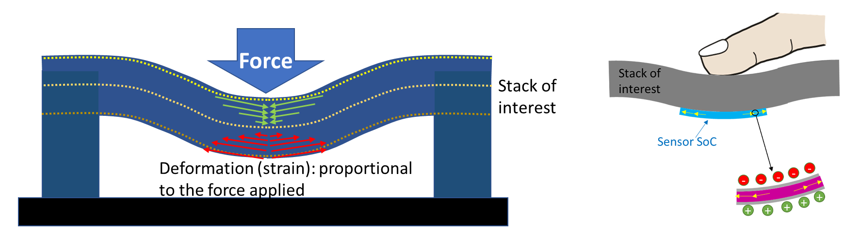
With in-plane designs the A surface sits in the XY plane, and the strain sensor measures XY strain deformation. At first order, the force applied is linearly proportional to the strain (deformation); by measuring that strain the amount of force can be back calculated (Figure 2). What impacts the deformation is the location of supporting pillars. In this example the edge sidewalls act as A-surface supports that keeps the large flat surface in place. An effective design provides optimal support simulation for smooth deformation measurement.
With the automotive grade MEMS sensors available today, only the AC MEMS force sensors can operate in the direct lamination manner, offering the “in-plane” sensing capability, the thinnest design that is typically 10x or greater in thinness, and thinner than force pillar designs.
Force Sensor Technology (AC vs DC)
Force sensing, the ability to measure the force that is applied to a surface (or stack), is measured in newtons of force pressure, and as we have seen, is often backcalculated from the deformation measured by a strain gauge. But not all force sensors are created equal—some methods of measurement are “better” than others. Here, “better” means more accurate, more easily deployed, more flexible, or more manufacturable.
MEMS force sensors are available in AC and DC designs. Like other silicon-based technologies, they offer good price performance, and the automotive grade MEMS sensors pass AEC-Q100 specification including temperature tolerance.
MEMS Force Sensors
Generally, MEMS force sensors offer the best economics and integration capability, but not all MEMS are created equal. The two forms are:
- DC Piezo-Resistive MEMS
- AC Piezo-Electric MEMS
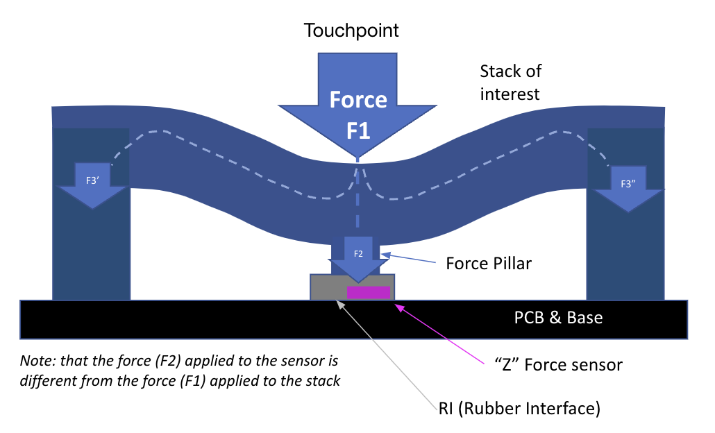
A] DC Force Sensor
The DC Piezo Resistive “Z” force sensor requires the addition of a force pillar and a rubber interface for manufacturing tolerances. The force applied to a stack is through a mechanical structure that transfers the force being applied to the stack to the force sensor (Figure 3) above. It is important to note that the force applied to the sensor in this configuration would not be the same force that is applied to the stack—necessitating calibration, and risk of multiple calibrations as the system design gets more mechanically connected to other systems of the vehicle. (This will be covered in more detail in the Force Sensing with DC – 201 Technical Blog)
Challenges with DC force sensor implementation
There are several challenges with a DC force sensor implementation, we’ll discuss the two main ones:
1) temperature/humidity and 2) residual stress.
Temperature/Humidity Impact
First, the mechanical interface is subject to material deformation due to temperature or humidity changes, making one-time calibration nearly impossible. In addition, it is subject to wear and tear and eventually reduces the life of the assembly. Furthermore, the Z force sensor requires a mechanical design that is optimized for delivering uniformity across a module of buttons, necessitating additional pillar(s), which often translates to modules with greater thickness to improve performance consistency.
Residual Stress
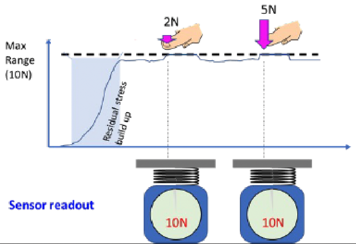
But the primary challenge of embedding a DC force sensor in an assembly free from residual stress. Residual stress is a by-product of cumulative manufacturing tolerances that create different combinations of pressures on an assembly. Those pressures put “phantom” pressures on the force sensor that can skew the stress values that are reported—or overload the sensor such that the range of the sensor is exceeded. Even worse, residual stress can change as an assembly is incorporated into other assemblies—resulting in repeated calibration events that would not be foreseen in the initial system design (Figure 4).
As an example, a home “weight scale” uses a DC sensor. When someone wants to weigh themselves, the scale needs to be zeroed out— this calibration is sometimes referred to as baseline self-calibration, which offers a self-healing capability as it zeroes out the residual stress.
The challenge is that if the DC sensor scale cannot sit freely, as is the case in a system assembly in a car, the residual stress affects measurement accuracy because it can’t effectively get “zeroed out.” The residual stress can be compensated for during assembly, but throughout the life of the system there will be limitations on the force sensing capability. Temperature and component aging also introduces high variability in performance, particularly when combined with rubber interfaces).
B] AC Force Sensor
An AC force sensor is based on a solid-state, on-die piezoelectric transducer that measures strain and deformation by generating charge/voltage signals when it detects strain (Figure 5). The key attribute of the transducer is that it seeks a charge-neutral state. As a result, after a deformation event the transducer will “self-calibrate” by returning to a zero-volt state, even if the deformation persists (Figure 6).
The opposite effect happens when the strain/deformation is released, and the piezo element returns to its original dimensions. In this case, a negative charge voltage signal is generated, but just like the positive press event, the negative charge will eventually leak away, and the piezo-element comes back to charge-neutral. Because of this behavior, the piezoelectric sensor is often categorized as an “AC sensor” that detects the AC/transient deformation behavior of a system.
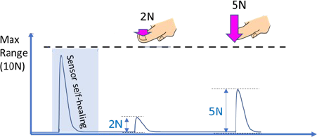
The main advantage of the AC sensor is that it can self-calibrate between events. It only reacts to a “transient event” within a short amount of time—for example, a finger press—but rejects all low-frequency events such as temperature drift or residual stress build-up caused by assembly actions during manufacturing.
It is important to note that some AC force sensors such as the UltraSense AC force sensor technologies can operate in both mechanical designs 1) Force Pillar (Z- strain) and 2) In-plane (XY strain). Operating in both mechanical designs gives the OEM the greatest amount of flexibility to support the broadest number of designs—including legacy DC force and new “in-plane” designs. (See blog on In-plane Sensing 101.)
AC Sensors and Residual Stress
Unlike the DC sensor, which is unable to recalibrate between deformation events (like in a system assembly), the AC sensor continues to provide accurate values regardless of the stresses surrounding it. In our previous example of residual stress (Figure 4), despite the residual stress of 10N approaching or exceeding the allowable values of a DC sensor, that stress is constant and would not change rapidly over time. As a result, an AC sensor would only react to the stress at the moment it’s applied—e.g., the moment it is placed in an assembly. After assembly, the charge signal from the 10N stress would leak out and sensor readout would come back to neutral (0N). No matter how much residual stress is created during assembly, the AC sensor makes full detection range available for press detection through the entire life of the assembly.
Good AC sensors offer differential signal support which is enhancing performance even more. (This will be covered in AC-DC Sensors – 201 Technical Blog).
A concern with AC is that it cannot provide measurements over an extended period, but with a good design, presses and corresponding gestures are typically of short duration. Generally measured in seconds, the longest may be a press-n-hold gesture such as a press-n-hold for 10 seconds. This AC approach provides support for a long press gesture. (This will be covered in Gestures – 101 & 201 Technical Blogs).
Summary
In this article, we’ve introduced the four key elements required to develop the next-generation HMI technology: sensing, processing, feedback, and secure connectivity. This chapter concentrated on force sensing and the most common solid-state mechanical designs and illustrated the differences between an AC versus a DC force sensors as used in automotive HMI applications, specifically the advantage of the newer AC piezo-electric sensor technology. Quality AC force sensors are the most versatile, as they can be used in both 1) Force Pillar (Z) physical and 2) in-plane (XY) design applications. This is especially important in that if you have an existing force pillar design you can apply the AC force sensor, and if you are creating a new design, you can use the slimmer in-plane sensing design that only the AC force sensor provides.
AC force sensing offers multiple benefits related to manufacturing assembly where residual stress can make equivalent DC sensor solutions more costly, difficult to integrate, and suffer from increased reliability from exposure to thermal and humidity environments.
AC Force Sensing technology checklist
Key feature checklist to look for in force sensing technology for automotive applications:
- Automotive Grade: AEC-Q100 compliance for IC, AEC-Q200 for passive components
- Baseline Self-Calibration (Self-Healing) Calibration: ability to adjust to changing conditions caused by environmental temperature, humidity, and resistance to stack
- InPlane Sensing: Capability to offer thin sensing, where the thickness is determined by the A-Surface thickness (stack) plus the sensor module board (which can include sensor, illumination, and haptic components)
- Ability to support the most common designs, which operate with either
- Force Pillar designs using Z force sensing.
- InPlane using XY force sensing
All UltraSense Systems force sensors and TouchPoint HMI controllers use AC piezoelectric sensing, including the CapForce, UltraForce, and TapForce HMI controllers and the QuadForce sensor. All of these touchpoint force sensors are quad force sensors and offer additional superior force sensing functions made possible by using the HMI controller’s MCU and Algorithm functions. (See the upcoming blog on: HMI Controller MCU & Algorithm 101 blog).
Questions or comments please give us feedback and we will share more objective details in future blog series. For more information, visit www.UltraSenseSys.com.
FAQ
Q: Some may ask if piezo is material supply-chain concern?
A: Supply Chain, with respect to availability is tied to the amount of material needed in high-volume production. In AC Piezo force sensing (as opposed to Piezo haptics which need large transducers that requires a higher multiple of more material compared to the piezo sensor,) it’s small size equates to small material quantities and results in no supply-chain concerns.